In this guide, we will demonstrate the operational principles of the vl530x time-of-flight sensor. Furthermore, we will exemplify the construction of a modest yet intriguing project by leveraging this cost-effective sensor in conjunction with the espressif systems’ esp32 board and the arduino IDE. The primary objective of this tutorial is to showcase electronic embedded designs that prioritize traits such as low power consumption, compact form factor, and portability facilitated by the utilization of rechargeable batteries.
For this tutorial, we assume that you have some intermediate level of experience working with the Arduino, ESP32, and the Arduino IDE. We have included a resources section that includes links to videos and articles related to topics covered in this tutorial.
Table of contents
In this tutorial we will cover the following main topics:
- Parts list
- Where to buy parts
- Introoduction to the VL53l0X time of flight sensor
- How-does-the-VL53l0x-work?
- Vl53l0X features
- Introduction to the KY-006 Buzzer
- Introduction to the DF Robot Beetle ESP32 C3 – RISC-V
- Project
- Circuit diagram
- Circuit pin connections
- Arduino Sketch
- How the code works
- Conclusion
- Links to additional resources
Parts list
- VL53l0X time-of-flight sensor
- KY-006 buzzer
- DF Robot Beetle ESP32 C3 – RISC-V
- Battery LiPo 500mAh 3.7V
- Battery Holder with switch – 2 x AA/9V Battery Holder + Switch + Wire
- Jumper wire
Where to buy parts
These parts can be purchased on many online stores including Ali Express, Amazon, Banggood. Some popular South African distributors include Microrobotics, Pishop, and Communica.
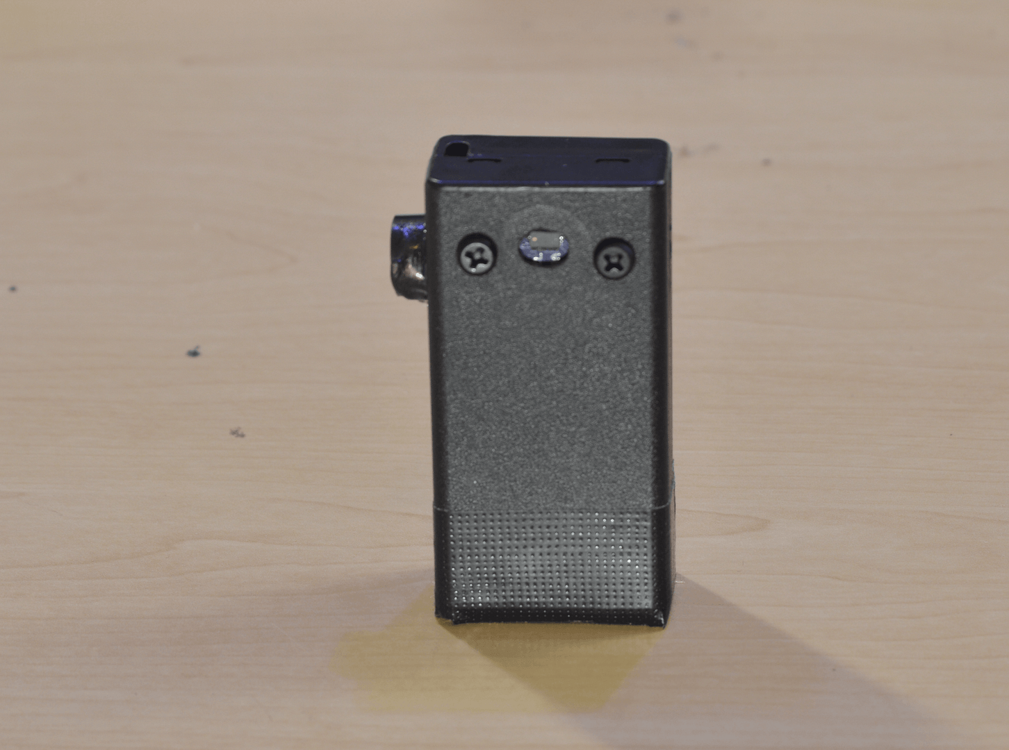
Introoduction to the VL53l0x time-of-flight sensor
The VL53L0X is a Time-of-Flight (ToF) laser ranging module. This sensor is used in applications that require accurate distance measurements. The sensor has a measuring range of up to 2m. The datasheet can be found here.

How does the VL53l0x work?
The sensor contains a very tiny, invisible laser source. During ranging, several infrared pulses are emitted from the laser, then reflected back by the target object. The VL53L0X can determine the time it takes for the emitted light source to hit the target object and return back to its receiver. This is called “the time of flight.”

Vl53l0X features
Some of the product features are listed below:
- Fully integrated miniature module (4.4 x 2.4 x 1.0 mm)
- Fast, accurate distance ranging
- Measures absolute range up to 2 m
- Eye safe
- Easy integration (I2C interface for device control and data transfer)
Vl53l0X technical specifications
- Package: Optical LGA12
- Size: 4.40 x 2.40 x 1.00 mm
- Operating Voltage: 2.6 to 3.5 V
- Operating temperature: -20 to 70°C
- Infrared emitter: 940 nm
Sensor Applications
- Access control (system activation and presence detection
- Robotics (collision avoidance, wall tracking,liff detection)
- Home appliance and Home automation
- Inventory management and liquid level monitoring
VL53l0X pinout
The module shown below has a 3.3v on board regulator. This means that the module can be supplied with a 5V or 3v3 microcontroller. The module dimensions will differ depending on manufacturer.

| Pin | Signal description |
| VCC | To be connected to main supply(2.6 – 5V) |
| GND | To be connected to main ground |
| SCL | I2C serial clock input |
| SDA | I2C serial data |
Introduction to the KY-006 Buzzer
The KY-006 Buzzer Module consists of a passive piezoelectric buzzer, it can generate tones between 1.5 to 2.5 kHz by switching it on and off at different frequencies either using delays or PWM.

KY-006 Buzzer specifications
- Operating Voltage: 1.5 – 15V DC
- Tone Generation Range: 1.5 – 2.5kHz
- Dimensions: 18.5mm x 15mm
KY-006 pinout
| Pin | Signal Description |
| – | Connected to ground |
| +(middle pin) | Connected to positive of supply from host(microcontroller) |
| S | This is the signal pin(PWMinput) |
Introduction to the DF Robot Beetle ESP32 C3 – RISC-V
The Beetle ESP32-C3 is a microcontroller designed for Internet of Things (IoT) applications. It is based on the ESP32-C3 RISC-V 32-bit single-core processor.
Presenting a compact board, measuring a mere 25 x 20.5mm, the Beetle ESP32-C3 offers a commendable total of 13 IO ports, facilitating effortless project development. By supporting integrated li-ion battery charging management, this remarkable board allows a direct connection to a li-ion battery, eliminating the necessity of additional modules. This thoughtful design ensures optimal size efficiency and operational safety in diverse application scenarios.
To enhance its functionality, the Beetle ESP32-C3 is equipped with an expansion board that provides additional power sources without increasing the product’s overall size. This feature facilitates convenient soldering. Additionally, the board is equipped with an easily connectable GDI, simplifying the process of using a screen without the need for complicated wiring.
The Beetle ESP32-C3 supports both WiFi and Bluetooth 5 (LE) dual-mode communication, thereby easing the challenges associated with networking. Furthermore, it is compatible with both the Bluetooth Mesh protocol and Espressif WiFi Mesh, enabling more stable communication and broader coverage.
Developers are afforded the flexibility to program the Beetle ESP32-C3 using various platforms, including Arduino IDE, ESP-IDF, MicroPython, with support for both C and Python languages.


ESP32 C3 specifications
- Operating Voltage: 3.3V
- Type-C Input Voltage: 5V DC
- VIN Input Voltage: 5V DC
- Operating Current: 25mA
- Maximum Charging Current: 400mA
- Operating Temperature: -40 ~ +105℃
- Dimensions: 25 x 20.5mm
Hardware specs
- Processor: 32bit RISC-V Single-core processor
- Main Frequency: 160 MHz
- SRAM: 400KB
- ROM: 384KB
- Flash: 4MB
- RTC SRAM: 8KB
- Clock: external crystal(32kHz); internal fast RC oscillator 17.5MHz(adjustable); PLL clock
- USB: USB 2.0 Up to 12Mbit/s
WI-Fi
- WiFi Protocol: IEEE 802.11b/g/n
- Bandwidth: Supports 20 MHz, 40 MHz bandwidth in 2.4GHz band
- WiFi Mode: Station, SoftAP, SoftAP+Station and promiscuous mode
- WiFi Frequency: 2.4GHz
- Frame Aggregation: TX/RX A-MPDU, TX/RX A-MSDU
Bluetooth
- Bluetooth Protocol: Bluetooth 5, Bluetooth mesh
- Bluetooth Frequency: 125 Kbps, 500 Kbps, 1 Mbps, 2 Mbps
Ports
- Digital I/O x13
- LED PWM 6 Channel
- SPI x1
- UART x2
- I2C x1
- I2S x1
- IR Transceiver: transmit channel x2, receive channel x2(random pin)
- 2 × 12-bit SAR ADCs, up to 6 channels
- DMA controller, with 3 transmit channels and 3 receive channels
Project
Upon acquiring a comprehensive understanding of the various components involved, we can proceed to integrate them into a tangible project. This tutorial aims to guide you through the systematic construction of a portable laser sensor, drawing inspiration from a memorable sequence in the film “John Wick Chapter 4”.
Circuit diagram

Circuit pin connections
| Component | Pin | Esp32 pin |
| VL53l0X | VCC | 3V3 |
| GND | GND | |
| SCL | 9 | |
| SDA | 8 | |
| KY-006 | VCC (+) | 3V3 |
| GND(-) | GND | |
| Signal(S) | 2 |
Arduino Sketch
Copy and paste the code into your arduino ide and upload it to your esp32 board. You can view the results in the serial monitor once the sketch has been successfully uploaded.
#include <Wire.h>
#include <VL53L0X.h>
const int freq = 2000;
const int ledChannel = 0;
const int resolution = 8;
const int buzzerPin = 2;
int dutyCycle=0;
int distance;
int test_distance;
VL53L0X sensor;

void setup()
{

  Serial.begin(115200);
  Wire.begin();

  sensor.init();
  sensor.setTimeout(0);
  ledcSetup(ledChannel, freq, resolution);

  // attach the channel to the GPIO to be controlled
  ledcAttachPin(buzzerPin, ledChannel);

  sensor.startContinuous();
  for(int i=0;i<15;i++){
   test_distance =sensor.readRangeContinuousMillimeters();
  delay(200);
  }
}

void loop()
{
   distance =sensor.readRangeContinuousMillimeters();
  //int distance =sensor.startContinuous(100);
  Serial.print("Distance: ");
  Serial.print(distance);
  Serial.print("mm");


  Serial.println();
  delay(20);
  if(distance<(test_distance*0.8)){
   dutyCycle = 20;
  ledcWrite(ledChannel, dutyCycle);
delay(300);
ledcWrite(ledChannel, dutyCycle*4);
delay(400);
ledcWrite(ledChannel, 0);
  }
}
How the code works
We start by importing all the necessary libraries. The Wire.h library enables us to use the i2c communication, and the VL53L0X.h enables us to use predefined functions that make it easier to communicate with the laser distance sensor. The VL53l0X library can be downloaded here.
#include <Wire.h>
#include <VL53L0X.h>
The ESP32 has a LED PWM controller with 16 independent channels that can be configured to generate PWM signals with different properties. The LED PWM controller function can be used to control other output devices such as DC Motors, buzzers, and LED lights. In our case we define the parameters for the PWM that will be used to generate a tone for our passive buzzer. Since the buzzer can operate at a frequency between 1.5kHZ and 2.5kHZ, we chose to set the frequency at 2kHZ.
First, you need to choose a PWM channel. There are 16 channels from 0 to 15.
const int ledChannel = 0;// Choose a LED channel (we chose channel 0)Then, you need to set the PWM signal frequency. For the passive buzzer, a frequency of 2000 Hz is fine to use.
const int freq = 2000; //set frequency of 2kHZYou also need to set the signal’s duty cycle resolution: you have resolutions from 1 to 16 bits. We’ll use 8-bit resolution, which means you can control the brightness using a value from 0 to 255. This value will be used to specify our duty cycle.
Resolusion = 2n-1 where n is the number of bits. So for example if we choose 8 bits than we have : 28-1, which is equal to 255. You can choose a resolution of your choice depending on the target application.
const int resolution = 8;To control the signal, you need to specify which GPIO or GPIOs it will appear on.
const int buzzerPin = 2; //GPIO for connecting buzzerHere, we innitialize the duty cycle at 0 , this means that the buzzer will be off in the beginning.
int dutyCycle=0;Initialize the variable that will hold the distance value
int distance;//Initialize variable to hold distance valueInitialize the int_test variable, this is the variable that will be used for storing the initial value(Gap between the door)
int test_distance;//Initialize valiable to hold the test_distance valueCreate an object called sensor
VL53L0X sensor; // create an object called sensorIn the setup(), we set a baudrate of 115200 for the serial port, we initialize the I2C communication with Wire.begin(), and we disable the timeout function by setting its argument to 0. The timeout function is a useful function if you want to be able to test if the VL53l0X sensor is functioning properly, but it does halt the entire program if it ocurs so I set it to 0 for my particular project.
  Serial.begin(115200);
  Wire.begin();

  sensor.init();
  sensor.setTimeout(0);// dissable timeout function
Start continuous back-to-back mode (take readings as fast as possible). To use continuous timed mode instead, provide a desired inter-measurement period in ms (e.g. sensor.startContinuous(100)). I chose to use delays to simplify the code.
sensor.startContinuous();You need to configure LED PWM with the properties you’ve defined earlier by using the ledcSetup() function that accepts as arguments, the ledChannel, the frequency, and the resolution, as follows:
ledcSetup(ledChannel, freq, resolution);Next, you need to choose the GPIO you’ll get the PWM signal from. For that use the ledcAttachPin() function that accepts as arguments the GPIO where you want to get the signal, and the channel that is generating the signal. We’ll get the signal in the buzzerPin GPIO, that corresponds to GPIO 2. The channel that generates the signal is the ledChannel, that corresponds to channel 0.
ledcAttachPin(buzzerPin, ledChannel);In the for-loop we take fifteen distance measurements at 200 millisecond intervals, and store them in a variable called test_distance. This causes a 3 second delay during which you can place the sensor on the door frame. The value in test_distance will later be compared to any new readings to determine if the sensor has been triggered.
  for(int i=0;i<15;i++){
   test_distance =sensor.readRangeContinuousMillimeters();
  delay(200);
  }
In the main loop(), we are continuously reading the distance, and storing it in the distance variable. We then print the results to the serial monitor.
   distance =sensor.readRangeContinuousMillimeters();
  Serial.print("Distance: ");
  Serial.print(distance);
  Serial.print("mm");
if(distance<(test_distance*0.8)) compares the value in distance to that in test_distance. If the value in distance is smaller than that in test_distance, it means that the sensor has been triggered. We could have just said if(distance<test_distance) to compare the readings.
In my comparison, I have chosen to compare the reading to 80 percent of the total initial reading, this is because I estimated that given a maximum gap of 2m, a person passing through the beam would occupy about 40cm which is roughly 20% of the total sensor range. This means that the sensor should be able to work properly for any gap that is 2m or less.
By changing the duty cycle(ledcWrite(ledChannel, dutyCycle)) , we’re able to change the tone of the buzzer, the idea was to get it to sound more like a door bell just like in the movie. Hence we start with a duty cycle of 20 for 300 milliseconds, and then increase the duty cycle to 80 for 400 milliseconds to achieve a tone similar to that of a door bell.
  Serial.println();
  delay(20);
  if(distance<(test_distance*0.8)){//check to see if sensor triggered
   dutyCycle = 20;
  ledcWrite(ledChannel, dutyCycle);
delay(300);
ledcWrite(ledChannel, dutyCycle*4);
delay(400);
ledcWrite(ledChannel, 0);
Conclusion
This tutorial provides a comprehensive guide on constructing a basic portable electronic circuit powered by batteries, incorporating a sensor. The sensor employed in this particular example is readily interchangeable with a sensor tailored to your preferences. One can devise a portable air quality monitoring system, a portable motion sensor, a portable temperature sensor, or any other imaginative applications.
Although the the ESP32’s Wi-Fi and Bluetooth functionalities was not incorporated in this tutorial, it is entirely viable to leverage these features to establish a portable wireless sensor network tailored to your specific application. The forthcoming tutorials will delve into techniques for enhancing power efficiency and optimizing this application.
Links to additional resources
ESP32: How to Setup An Analog Output for LED dimming, DC motor control, Etc
ESP32 PWM with Arduino IDE (Analog Output)
Using VL53L0X 200cm Laser Distance Sensor | Arduino Step By Step Course
Getting started with the esp32
If you found this tutorial helpful, we would greatly appreciate it if you could take a moment to leave a comment and subscribe to our email list. We value your feedback and would love to hear from you.
Additionally, if you believe in our mission and would like to contribute to our growth, kindly consider visiting our donation page and making a small contribution. Your support means a lot to us. Thank you.